| The R-390A Frequently Asked Questions Page |
|---|
|
|
| A large number of equipment arrangements and environments utilized the R-390A/URR. Some accessories and arrangements are used in several combinations. This document is a compilation of the wisdom shared by members of the online community of R-390A enthusiasts. As such, it is advice to those who endeavor to maintain and restore the R-390A family of receivers. The information is shared without warranty, expressed or implied. This information is in the public domain and can be freely copied or shared. Appropriate attribution is appreciated. |
|
AN/FLR-7 |
This Wullenweber antenna, also known as a Circularly Disposed Antenna Array
(CDAA), consisted of a large number of 200 foot towers arranged into a ring more
than 1300 feet in diameter.  An inner ring of shorter towers completed the array.
The antenna reportedly operated from VLF well into the VHF frequency range.  It
provided direction finding accuracy to within two or three degrees, according to
some reports.
|
|
AN/FLR-9 |
The AN/FLR-9 antenna array is composed of three concentric rings of antenna elements.
Each ring of elements receives rf signals for an assigned portion of the 1.5 - to - 30
Mhz radio spectrum.

The outer ring nominally covers the 2 - to - 6 Mhz range (Band A), but also provides
reduced coverage down to 1.5 Mhz.   Band A contains 48 sleeve monopole elements spaced
78.4 feet apart (7.5 degs.) about the circumference of a circle, the radius of which
is 599 feet.

The center ring covers the 6 - to - 18 Mhz range (Band B).  Band B contains 96 sleeve
monopole elements spaced 37.5 feet apart (3.75 degs.) about the circumference of a
circle, the radius of which is 558 feet.

Bands A and B elements are vertically polarized.  A vertically-polarized
reflecting screen is required for the Band A and B antenna elements. This screen is
located 20.5 feet inside the Band B antenna ring and mounted on a support structure.
Its working radius is 538 feet.  A common ground screen is provided for the Band A
and B antenna array. This screen projects approximately 96 feet out from the reflecting
screen support structure. Radial wires extend outward an additional 88 feet from the
end of the ground screen.

The inner ring covers the 18 - to - 30 Mhz range (Band C). Band C contains 48 antenna
elements mounted on wooden structures placed about the circumference of a circle whose
radius is 167.25 feet around the central building.   Band C elements consist of two
horizontally polarized bow-tie planar dipole antenna subelements electrically tied
together, and positioned one above the other.  These elements are mounted on a support
structure, and protrude away from the support structure, a distance of 10.25 feet.
A horizontally-polarized reflecting screen is mounted on the same B and C support
structure. This screen has a working radius of 157.33 feet.

Signals from the individual antenna elements are transmitted to the central building via
7/8-inch low-loss coaxial cable.  The central building houses only the antenna system
electronics. An operations building located approximately 1000 feet from the central
building houses the intercept and DF ops and their receivers and associated equipment.

The system is designed to locate and intercept signals with an accuracy of plus or
minus three degrees or so over frequencies ranging from VLF (30 KHz) to VHF
(30 MHz) and above.

Manual: TM-32-4940-201-15,   "Monitor and Test Group Countermeasures Receiving Set
                              AN/FLR-9 (V7)(V8), 1976-Jun-30
        TM 32-5895-232-15/4, "RF Matrix Group, Countermeasures Receiving Set
                              AN/FLR-9(V8)", 1976-Dec-31
        TM 32-5895-233-15,   "System COntrol Group, Countermeasures Receiving Set
                              AN/FLR9(V7)(V8), 1976-Jun-25
        TM 32-5895-234-15,   "Intercept Group, Countermeasures Receiving Set
                              AN/FLR-9(V7)(V8), 1975-Jan-04
        TM 32-5895-235-15/2, "Direction Finding Group, Countermeasures Receiving Set
                              AN/FLR-9(V7)(V8), 1976-Jun-30
        TM 32-5985-217-15,    "Antenna Group, Countermeasures Receiving Set
                              AN/FLR9(V7)(V8), 1976-Jun-25
        TM 32-6625-260-14,    "Operator, Organizational, DS and GS Manual, Test Set
                              Beam Selection ID Unit TS-3283/FLR-9", 1972-Nov-01
        TM 32-6625-261-14,    "Operator, Organizational, DS and GS Manual, Calibrator,
                              Beam Selection ID Unit TS-3284/FLR-9", 1972-Nov-01
|
|
AN/FRD-10 |
The AN/FRD-10, another smaller version of the AN/FLR-7 antenna, is also a Wullenweber
design.  The antenna consists of (from outermost ring to innermost):

    a 900 foot ring of 120 vertical antenna elements, spaced every three degrees

    a reflector screen for the 120 vertical antenna elements

    a ring of forty folded monopole antennas

    a second reflector screen, this one for the monopole antennas.

Inside of the inner ring, an operations center was located where the antenna
switching and distribution system sent signals to a large number of individual
intercept operators, each equipped with one or more R-390(*)/URR or other receivers.
|
|
"T2FD" |
Harris Corporation made several models of the Tilted Terminated Folded Dipole
("T2FD") antenna that was used by various government and civilian agencies with the
R-390(*)/URR and other receivers.

The Barker and Williamson Corporation obtained a patent (U.S. Patent #4423423)
for their specific T2FD antenna design.

The T2FD is a broadband folded dipole antenna design that provides a relatively
stable feed point impedance over about a five to one frequency range.  The antenna
length in meters is approximately 100 divided by the lowest desired operating
frequency in megahertz.  The upper element of the folded dipole is opened in the
center and a non-inductive terminating resistor of around 350-400 ohms is inserted.
The bottom element is fed in the center through a 6-to-1 balun for a good match to
50 ohm feed line.

The antenna is not as efficient as a matched half wave dipole at any specific
frequency, but it also does not require an antenna tuner for operation, making it
easy to use.  The loss of receiving efficiency is not generally noticeable
in the high frequency range (2-30 MHz), amounting to less than 6 db (one standard
S-unit) during extensive on-the-air testing.
|
|
System, AN/GRC-26 |
The AN/GRC-26D is a shelter mounted HF RTTY communications system. It
operated from mobile, moveable, and fixed locations. It used the T-368/URT
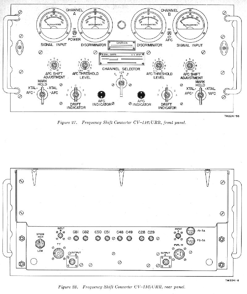
transmitter (see below), R-390 or R-390A/URR receivers, a CV-116 RTTY converter, a
LS-206A/U speaker unit and TT-59 teletypewriters.
Manual: TM 11-264, "Radio Set AN/GRC-26", 1950-Dec-11
TM 11-5820-202-10 "Operator's Manual Radio Sets AN/GRC-26A, B and C",
1959-Jan-07
TM 11-5820-256-10 "Operator's Manual Radio Set AN/GRC-26D", 1969-Jun-19
TM 11-5820-202-20 "Radio Sets AN/GRC-26A, B and C Organizational
Maintenance", 1959-Jan-07
TM 11-5820-256-20 "Radio Sets AN/GRC-26D Organizational Maintenance
Manual", 1962-Jan-05
TM 11-5820-256-35 "Radio Sets AN/GRC-26D, DS, GS and Depot
Maintenance Manual", 1967-Feb-08
TM 11-5062, "Frequency Shift Converter CV-182( )/GRC-26, 1952-Aug-22
TM 11-2241, "Frequency Shift Converter CV-116( )/URR, 1955-Mar-28
TM 11-2241 C.1, "Frequency Shift Converter CV-116( )/URR, 1956-Oct-31
TM 11-2241 C.2, "Frequency Shift Converter CV-116( )/URR, 1957-Apr-11
TM 11-809-10, "Radio Transmitters T-368( )/URT 1958-May-14
TM 11-809-20, "Org Maint Manual Radio Transmitters T-368( )/URT,
1958-Jul-02
TM 11-809-35, "Field and Depot Maintenance Manual Radio Transmitters
T-368( )/URT, 1958-Dec-08
TO 31R2-GRC26-31, "Remote RTTY Operation with AN/GRC-26A Using Neutral
Loops", 1952-Mar-14
TO 31R2-2GRC26-81, "Radio Set AN/GRC26D", 1962-Nov-06
TO 31R2-2GRC26-132, "Maintenance manual, Radio Set An/GRC-26D", 1964-Jun-10
TO 31R2-2GRC26-251, "Operator's manual Radio Set AN/GRC-26D", 1961-Jul-20
TO 31R2-2URT-121, "Operator's manual, Radio Transmitters T-368( )/URT",
1958-May-14
|
|
System, AN/GRC-41 |
The AN/GRC-41 HF communications system operates on CW/AM in half-duplex or
full-duplex operation.  It offers mobile, fixed, or semi-fixed operation.  Major
components of the system are the T-368(C) transmitter and R-390 receiver.
|
|
System, AN/GRC-129 |
The AN/GRC-129 is a one kilowatt PEP SSB communications system operating over
a frequency range of 2-30 MHz.  By incorporating SSB capability, this system
claims a two-to-one advantage over AM systems.

It consists of a modified AN/GRC-26D that transmits and receives SSB, AM,
CW, and FSK. The AN/GRC-129 communications system uses a pair of R-1247
(see 'Variations' section) receivers, a pair of CV-1694 SSB demodulators and
a T-946 transmitter for HF SSB and RTTY operation.
|
|
System, AN/MRT-9 |
The AN/MRT-9 HF RTTY communications system uses an aircraft or vehicular
transportable shelter to house three T-368/URT transmitters and one R-390(*)
receiver.

Manual: TM 11-5820-352-15 "Transmitting Set, Radio, AN/MRT-9", Date Unknown
|
|
Desktop CY979A |
TBD
|
|
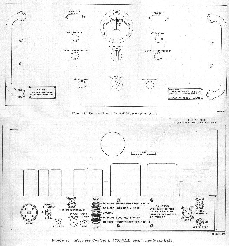
Receiver, C-975 |
|
|
Frequency Shift CV-116 |
|
|
Frequency Shift CV-182 |
Manual: TM 11-5062, "Frequency Shift Converter CV-182( )/GRC-26, 1952-Aug-22
|
|
Frequency Shift, CV-305/U |
The CV-305U frequency shift converter accepts two channels (dual diversity) of
450-510 KHz input and provides 20/60 milliamp or polar output current for
electromechanical teletypewriters.  It operates with an R-390(*)/URR receiver and is
a part of the AN/GRC-26D communications system.
|
|
Antenna, CU-286/FRR-33 |
The  CU-286/FRR-33 antenna coupler is used in the AN/FRR-33 communications
system.  It covers 500kHz-32MHz in 6 bands.  It contains two identical gang tuned
amplified pre-selectors that are similar to the R-390(*)/URR RF deck.  The front
panel has one knob for tuning and one knob for band selection.  It has four inputs
for antennas and two outputs for receivers.  The unit does not support remote
operation.  The unit has twin-axial antenna connectors.
|
|
Audio Frequency, MX-2840/URR |
This transistorized unit takes input from the R-390A/URR or other 455 KC IF output
and provides an outboard audio stage.  It is 1.75 inches high and is rack mounted.

The manual indicates "National Security Agency, Fort George G. Meade, MD,
October 1962.   Notes present in the manual suggest that only 39 units existed in
1961-1962.
|
|
Finding System, AN/TRD-15 |
The AN/TRD-15 Direction Finder uses the R-725 receiver (see 'Variations' section).

Manual: TM 11-5825-231-10, "Direction Finder Sets AN/TRD-15 and AN/TRD-23",
                            1973-Feb-15
        TM 11-5825-231-24, "Organizational DS & GS Maintenance Manual - Direction
                            Finder Sets AN/TRD-15 and AN/TRD-23", 1973-Aug-31
        TM 11-5825-231-25,
        TM 11-5825-231-34P1, "DS and GS Depot Maintenance Parts List - Direction
                              Finder Sets AN/TRD-15 and AN/TRD-23, Date Unknown
|
|
SSB, CV-157/URR |
The CV-157/URR SSB/RTTY demodulator uses 44 tubes, weighs 105 pounds and occupies a 10.5 inch high rack space. It converts the IF output of an R-390(*)/URR receiver into voice or 8 channels of RTTY and feeds it to two separate telephone lines. |
|
SSB, CV-591/URR and CV-591A/URR |
The CV-591(A) SSB demodulator uses the 455 KHz IF output signal from the
R-390A/URR to implement remotely controllable USB and LSB operation.   It is
rack mounted, 5.25 inches high and weighs approximately 25 pounds.  The TMC
model number for the CV-591/URR is MSR-1. The TMC model number for the
CV-591A/URR is MSR-4.

Manual: 0967-LP-051-2010, "Instruction Book for SSB c\Converter CV-591A/URR",
                           1967?
        0967-LP-051-2020, "CV-591A/URR Addition of Field Load Resistor", 1961-Feb-27
        0967-LP-051-2040, "CV-591A/URR Maintenance Standards Tests", Date Unknown
        0967-LP-051-2042, "CV-591A/URR Change to Maintenance Standards Book",
                           1969-Aug
        0967-LP-051-2050, "CV-591A/URR Reduction of Shock Hazard", `1967-Feb
        0967-LP-051-2060, "CV-591A/URR Reduction of Heat and Power Supply Failures",
                           1974-May
        0967-LP-051-2070, "CV-591A/URR Reduction of 17KHz Feedthrough", 1966-Dec-01
|
|
SSB, CV-1694/GRC-129 |
The CV-1694/GRC-129 SSB demodulator operates with the R-1247 (see 'Variations'
section) /GRC-129 receiver.  It is 3.5 inches tall and fits a standard 19 inch rack
space.  It works with any receiver that has 455 KHz IF output.
|
|
SSB, CV-1758/URR |
The CV-1758/URR SSB demodulator uses the 455 KHz IF output signal from the
R-390A/URR receiver to implement remotely controllable USB and LSB operation.
It is rack mounted, 5.25 inches high and weighs approximately 25 pounds.  It was
manufactured by the Technical Materiel Corporation (TMC).  The TMC model
number for the CV-1758 is MSR-9.
|
|
PP-629/URR |
The PP-629/URR power supply is used in the AN/FRR-33 receiving system to
power the autotune mechanisms in two R-391(*)/URR receivers.
|
|
Receiver CU-168/URR |
The CU-168/FRR receiver multicoupler is an antenna distribution amplifier that
feeds up to five HF receivers.  It's Input and output impedance is 70 ohms.   The
unit is unusual in that it uses four 12AU7 tubes in parallel for each amplifier stage,
with the two halves of each tube also in parallel.

Manual: TO 31R1-2FRR-1, "Antenna Coupler CU-168/FRR", 1957-Jun-28
|
|
Receiver CU-1388/FLR-9 |
The CU-1388/FLR-9 receiver multicoupler is an antenna distribution amplifier that
feeds up to eight HF receivers.  It is used in the AN/FLR-9 radio direction finding
system to feed signals from the Wullenweber antenna array to the R-391(*)/URR
receivers.
|
|
Receiver CU-1638/GR |
The CU-1638/GR receiver multicoupler is an antenna distribution amplifier that
feeds up to six HF receivers.  It is rack mounted, 3.5 inches high, and weighs
approximately 15 pounds.
|
|
Receiving AN/FRR-33 |
Collins Radio Company manufactured the AN/FRR-33 HF RTTY receiving system.
The unit provides dual-diversity reception by using two receivers and space diversity
by using multiple antennas for each receiver. Local or remote control, using a
telephone dialing system, selects one of eight preset channels in each receiver.
It is equipped with:

    Antenna Coupler, CU-286/FRR-33,

    Two Radio Receivers, R-391(*)/URR or R-725 (see 'Variations' section),

    Selector Control, C-974/FRR-33,

    Receiver Control, C-975/URR,

    Power Supply, PP-629/URR.

Manual: TO 31R2-2FRR33-11, "Radio Receiving Set AN/FRR-33", 1955-Apr-14
|
|
Receiving AN/FRR-34 |
The AN/FRR-34 HF receiving system utilizes three R-390(*)/URR receivers in a
triple diversity configuration.  It uses a C-1012 Control Monitor for receiver control
and selection.  It uses a KY-82/FRR RTTY keying unit for diversity signal selection
and generation of a signal for remote operation of RTTY apparatus.

Manual: TO 31R2-2FRR34-1, "Radio Receiving Set AN/FRR-34", 1955-May-04
        TO 31R2-2FRR34-24, "Repair parts and Special Tools Lists, Receiving Set
                            AN/FRR-34", 1962-Feb-14
|
|
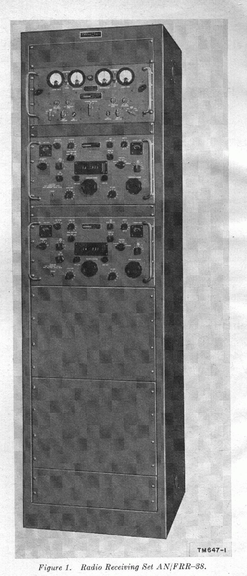
Receiving AN/FRR-38 |
|
|
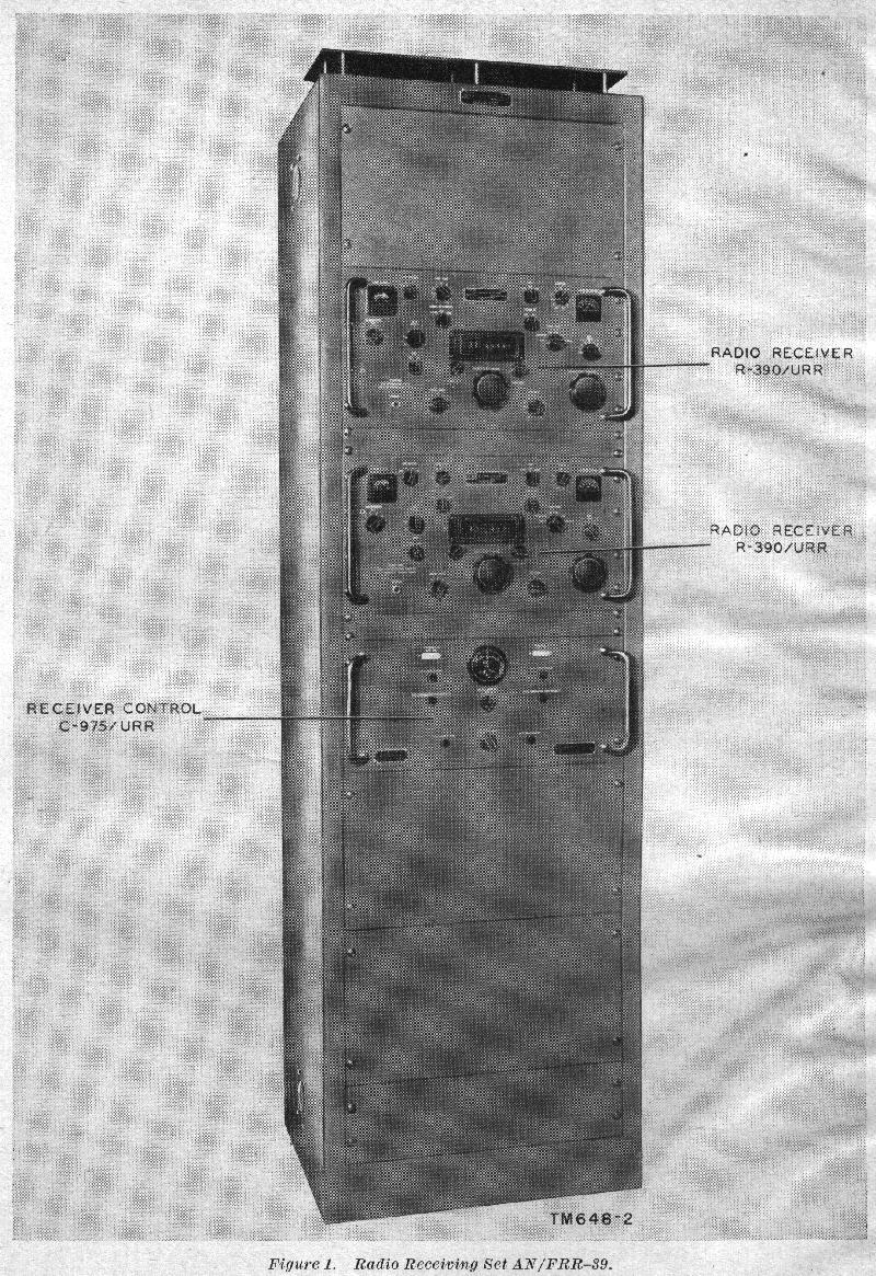
Receiving AN/FRR-39(*) |
The AN/FRR-39(*) HF receiving system utilizes two R-390(*)/URR receivers.  This
system consists of:

    two R-390(*) radio receivers,

    C-975(*)/URR receiver control,

    CY-1119(*)/V electrical equipment cabinet.
|
|
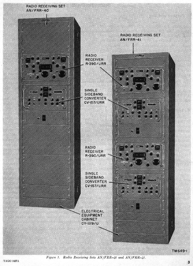
Receiving AN/FRR-40 and AN/FRR-41 |
|
|
Receiving AN/MRR-8 |
The AN/MRR-8 HF RTTY receiving system is housed in an aircraft or vehicle
transportable shelter.  It is equipped with:

    Eight R-390(*) /URR receivers

    RTTY equipment,

    diversity circuitry,

    security gear.
|
|
Control Unit, C-974/FRR33 |
The C-974/FRR-33 selector control unit received 455 KHz IF output from the
R-391(*) receivers, converted that signal to audio, processed it through an AGC
network, and fed the result back to the source receiver.  The receiver's audio output
then fed separate FSK demodulators. The control unit could address any of the
receivers in the AN/FRR-33 receiving system. The selector used a mechanical
telephone dial for control.
|
|
LS-166 |
The LS-166 loudspeaker unit contains a small low impedance speaker housed in a
metal enclosure with a 600 ohm to 8 ohm transformer to match the R-390A's local
audio output impedance.
|
|
LS-206A/U |
The LS-206A/U is a dual speaker unit for the R-390A.  It contains two speakers
mounted on a rack panel with matching transformers for the 500 ohm audio line
from the receivers.  It is a part of the AN/GRC-26D HF communications system.
|
|
AN/SRT-14 |
AN/SRT-14 Transmitters were common on Navy ships and often operated in
conjunction with R-390(*)/URR receivers.  This transmitter operates from 300 KC to
26 MC and is adjustable in 10 cps steps.  It uses a 4-400 tube in the final amplifier
modulated by a pair of 807 tubes giving 100 watts out on AM and 150 watts out on
CW and FSK. With the addition of the OA-685/SRT Radio Modulator-Power Supply
Booster, the output power becomes 500 watts on AM, CW and FSK.
|
|
T-368/URT |
The T-368/URT transmitter is a HF transmitter covering 1.5 to 20 MHz in four
bands with 400 watts of CW/AM output.  It is about 42 inches high, 32 inches wide
and 31 inches deep.  It weighs approximately 700 pounds.   It was part of the
AN/GRC-26D HF communications system.

Manual: TM 11-809-10, "Radio Transmitters T-368( )/URT 1958-May-14
        TM 11-809-20, "Org Maint Manual Radio Transmitters T-368( )/URT,
                      1958-Jul-02
        TM 11-809-35, "Field and Depot Maintenance Manual Radio Transmitters
                       T-368( )/URT, 1958-Dec-08
Radio Boulevard has nice info on the T-368 here. |
|
T-946 |
The T-946 SSB transmitter is a highly modified version of the T-368/URT HF
transmitter.  The modification consisted of replacing the AM modulator section and
the RF amplifier section.  The T-368 speech amplifier drove an external SSB exciter
that then used the modified RF amplifier section as a linear amplifier.  The T-946
transmitter was operated with the R-1247 (see 'Variations' section) variant of the
R-390(A) in the AN/GRC-129 HF SSB communications system.
|
|
AN/WRT-2 |
The AN/WRT-2 transmitter was commonly used aboard navy ships in conjunction
with R-390(*)/URR receivers.  It covers 2-32 MHz with 500 watts of
AM/RTTY/SSB/ISB output power.  The cabinet is six feet tall.
|
|
|
|
|
|||
|
|